The Harkwood Sync-One2 is a tool designed to measure the AV sync error (audio/video synchronization error) of a full AV setup involving a source device, transport interface, and sink device. Examples include a cinema, a video production workstation, a specific Blu-Ray player paired with a TV and sound system, etc. It can be used to calibrate a setup based on the time it takes for sound to travel from the speakers to the listening position.
⚠️ Important notes regarding sink device(s):
It is not easy to accurately measure the AV sync error of only your sink device with this tool because you are just as likely to be measuring the AV sync error of your source as you are to be measuring the AV sync error of your sink device.
To measure the AV sync error that is specific to your sink devices, you can use these other methods.
Index
Using the Sync-One2
The Sync-One2 can be used to measure AV sync error in two ways:
- Direct audio connection using the external audio port on the Sync-One2
- Using the built-in microphone to measure AV sync error at a specific viewing/listing position
The direct connection is ideal for measuring AV sync error when headphones may be used. In fact, you can plug a monitor’s headphone output directly into the Sync-One2 for this purpose. It may also be useful when the viewing/listening position is not fixed and will be close to the speakers.
Using the built-in microphone enables measurement of AV sync error at a specific viewing/listening position because the time that it takes for sound to travel to the microphone will be accounted for in measurements.
Sync-One2 Accuracy
Test Method
These tests were performed in a dark room with the computer monitor’s brightness set to maximum. The “Audio Trigger Level” and “Video Trigger Level” were both left at their default high setting. The Sync-One2 firmware version was 2.2.0.
An oscilloscope was used alongside the Sync-One2 to assess the accuracy of its reported measurements. A simple photo transistor circuit was connected to the oscilloscope for video comparisons. When the Sync-One2’s external audio port was used, the same line level signal was split off and fed to the oscilloscope. When the built-in microphone of the Sync-One2 was used, a dynamic microphone was connected to the oscilloscope.
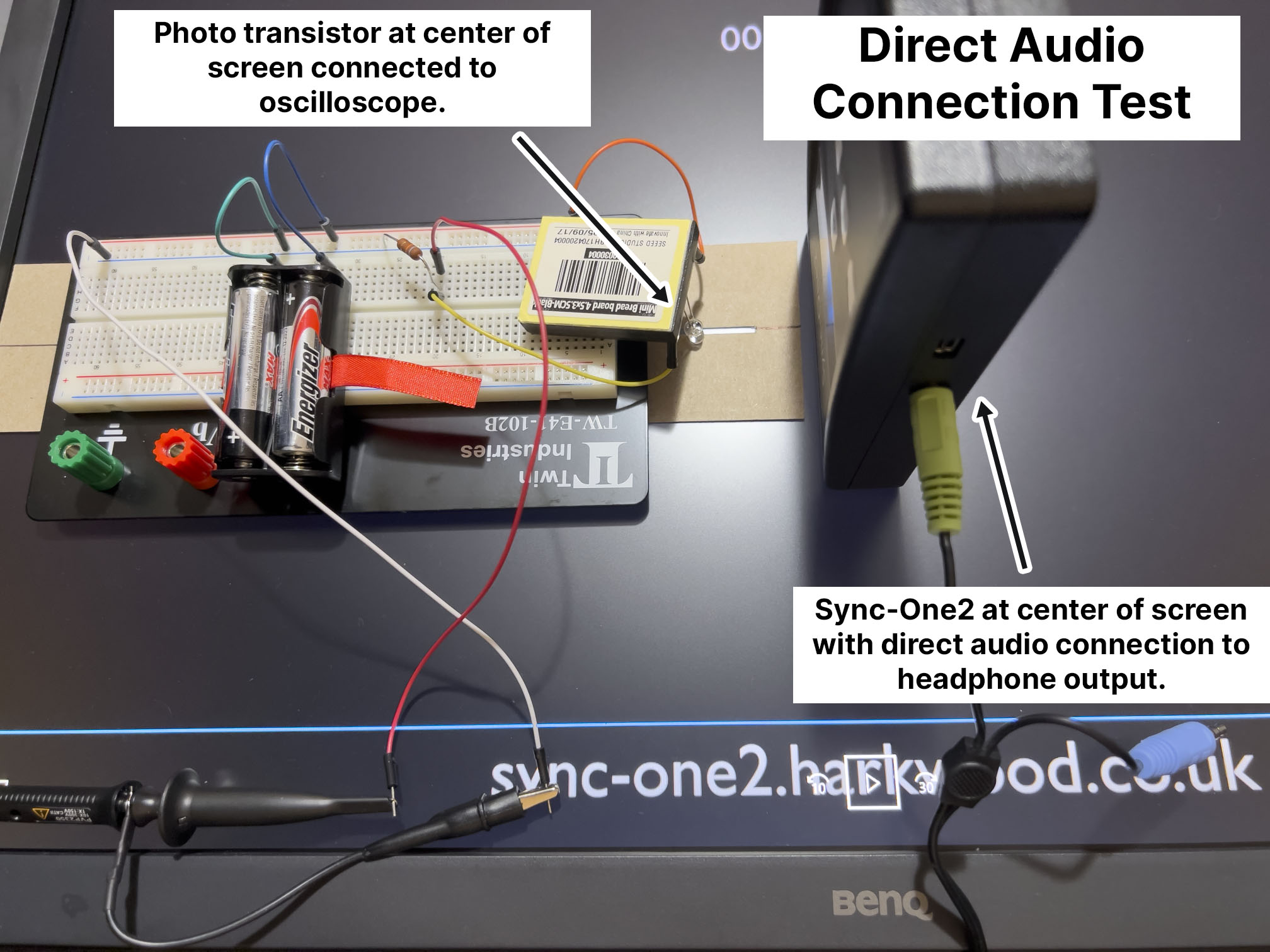

The photo transistor was placed at the center of the screen, which is appropriate for video latency and audio/video synchronization measurements, as discussed on the Advanced Topics in Video Latency and Audio/Video Synchronization page. The Sync-One2 was also positioned at the center of the screen when using a direct audio connection and pointed at the center of the screen when using the built-in microphone.
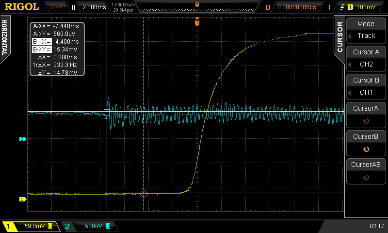
Interpreting Oscilloscope Measurements
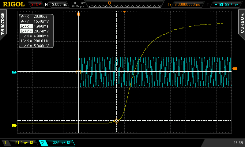
In the above oscilloscope screenshot, the yellow line represents the light detected by the photo transistor, and the blue line represents the audio signal. The time between the vertical solid line and the vertical dashed line is shown as ΔX, which is the AV sync error in this case.
Video latency, for the purposes of audio/video synchronization, can be measured at the earliest change in light or when the luminosity reaches 50% of its peak value. For more information on these two approaches, see the notes on LCD response time of the Advanced Topics in Video Latency and Audio/Video Synchronization page. On the monitor I was using for this test, the difference between first detectable change and 50% luminosity is about 2.3 ms, which is not a significant amount of time. It was clear that the Sync-One2 is designed to measure at the earliest detectable change, rather than the point that luminosity reaches 50%, but the threshold is dependent on display brightness and the Sync-One2’s “Video Trigger Level” setting. If you want to target a different luminosity than the earliest detected, it may be possible to perform Sync-One2 calibration with a brighter (grey) image instead of a black image on the screen.
Again, these tests were performed in a dark room with the computer monitor’s brightness set to maximum and the Video Trigger Level set to High.
Results: Direct “External” Audio Connection
When connecting the Sync-One2’s external audio port to the headphone output of the computer monitor, the results consistently matched the results shown by my oscilloscope.
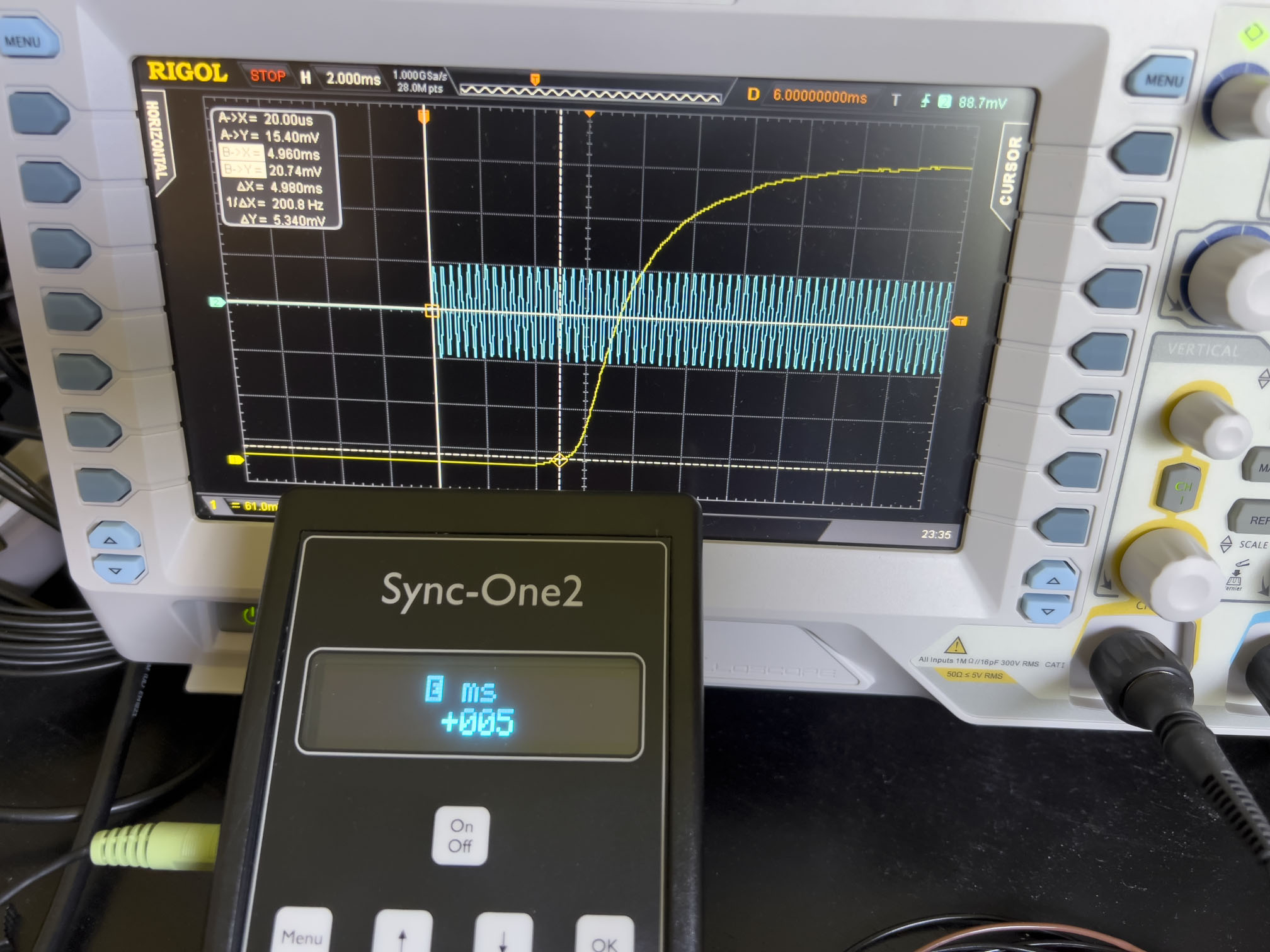
Any time the reported sync error changed from measurement to measurement, I would see my oscilloscope also show the different sync error. This immediate feedback made it clear that the reason that the sync error would change between different measurements was a stutter in my computer’s video playback and not due to an inconsistency with the Sync-One2.
Results: Built-In Microphone
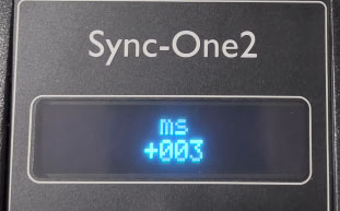
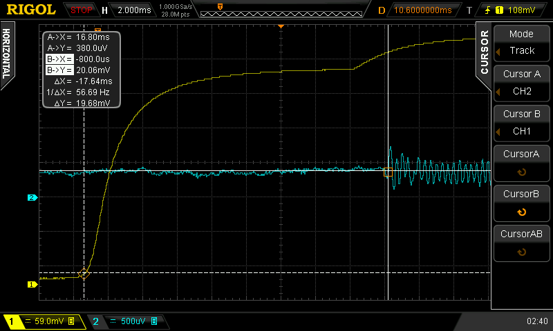
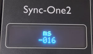
As previously described, the Sync-One2’s built-in microphone enables measurement of AV sync error at the intended viewing/listening position. This means it is no longer possible to place the Sync-One2 directly on the center of the display. Here is a comparison of the measurements from the oscilloscope, wired with a microphone, and the measurements from the Sync-One2:

Unlike when the the Sync-One2 was held close to the center of the screen, we can notice around a 4 ms difference between the Sync-One2 measurement and the measurement reported by the oscilloscope.
This behaviour occurs because the Sync-One2 will detect light from the top of the screen when it is positioned a distance away from the screen. This computer monitor refreshes its image from top to bottom, so light appears at the top of the screen before it appears at the middle of the screen. Theoretically, with a 60 Hz video refresh rate, the AV sync error measurement from the Sync-One2 could be as much as 8 ms lower than it should be, but in practice I only noticed a measurement of about 4 or 5 ms lower as shown above. This issue is specific to raster scanning displays.
This discrepancy of only a few milliseconds is acceptable for audio/video synchronization. Since most all displays refresh their image at 50 Hz or higher, I do not see this as a significant inaccuracy.
…But let’s see if we can do better:
How to Measure at the Center of the Screen from a Distance
Using an External Microphone
The first simple trick is to separate the microphone from the optical sensor of the Sync-One2. This can be done by plugging in an amplified or dynamic analog microphone to the Sync-One2’s external audio port. With some setups, this allows the microphone to be positioned at the listening position and the Sync-One2 to be positioned directly at the center of the screen.
I tried this with a Shure SM58 and XLR to 3.5 mm adapter with the Sync-One2’s Audio Trigger Level set to “high”. It did not work with my computer monitor because the speaker output was too quiet, but it worked fine with my other computer speakers when their volume was set high enough that I needed ear plugs. Using an amplified analog microphone with no delay would allow measurements at lower volume levels.
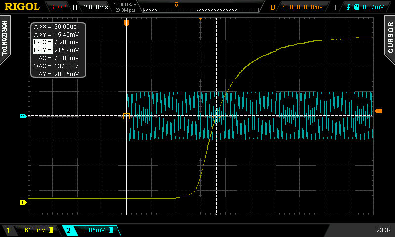
Blacking Out Half of the Video
If this external microphone setup isn’t viable or it is difficult to position the sensor directly on the center of the screen, you can simply black out the half of the test video file or physically cover half of the screen. Most displays refresh from top to bottom, so you will likely want to black out the top half of the video. To verify which way your display refreshes its video, simply move the Sync-One2 around your screen: areas with a lower AV sync error are refreshed first and areas with a higher AV sync error are refreshed later. The area that is refreshed first, usually the top of the screen, is the half of the screen that should be blacked out.
I tried modifying the video test file by blacking out the entire top half of the video and this was the result:

This technique resulted in an improvement: previously we saw a -3.7 ms discrepancy, but by blacking out the top half of the video we now see only a +1.6 ms discrepancy.
Again, this is a minor improvement on the accuracy of this tool, but it’s a simple trick to get the most accurate measurements at the center of the screen.
False Positives
When audio volume is loud, video display is bright, and trigger thresholds are set correctly, the Sync-One2’s performance seems to be extremely consistent and accurate. But when some of these conditions are not met, the Sync-One2 will report sync errors that are incorrect and these incorrect measurements will contribute to the average calculation and statistics.
In practice, this can sometimes make it difficult to tell if measurements are erratic because of a problem with video playback, a problem with Sync-One2 configuration, or a problem with the test environment. Because of this “false positive” behaviour, it is important that a user becomes familiar with the tool to identify when inconsistent measurements are due to a poor audio or video signal to noise ratio. For example, a user can turn up and down the volume of their speakers while using the Sync-One2 to find the point where measurements are stable.
As an example of this “false positive” behaviour, I used the Sync-One2 with a Sony XBR85X800H TV connected to my PC. The TV was set to Game mode and I used the 60 fps test video. I positioned the Sync-One2 about 7 feet (213 cm) from the TV. With the volume level set to at least 35 out of 100, the Sync-One2 consistently reported -84 ms or -83 ms, showing that the AV sync error was about -83.5 ms. When the volume of the TV was set to around 25 out of 100, the Sync-One2 would incorrectly a report a different value for every measurement, jumping between -85 ms and -553 ms, with most values being around -140 ms.
If the user suspects any measurements are invalid, due to background noise, etc., those measurements can be manually deleted in the “Show Stats” menu option. This feature allows the user to ensure that one-off incorrect measurements do not contribute to the average sync error calculation.
Video Files
Any video with a precisely synchronized flash and audio tone can be used with the Sync-One2. Video files for use with the Sync-One2 are provided on the support webpage. Netflix also has a number of Test Pattern videos, one of which is a video that can be used with the Sync-One2. Some Blu-ray calibration discs have suitable test patterns. You could even make your own video if you’d like. It’s important to test each device and setup with the Sync-One2, because each source will likely have a different sync error.
For the purpose of this review, we will be looking at the videos provided on the support website. The videos are quite simple: they consist of a two frame white flash with an audio tone that plays through the duration of the two frames.
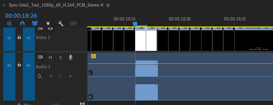
“Standard” vs. “Variable” Video Files
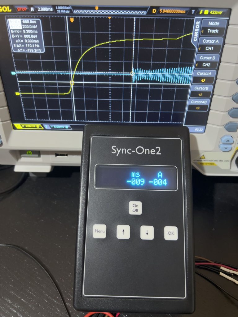
The “variable” video files are designed to account for variable video latency introduced by frame pull down. I tried out the 24 Hz “variable” video on a 60 Hz monitor and found that it was effective in reproducing a spread of AV sync error measurements that averaged out to the correct value. To view the the average AV sync error, select “Show Stats” from the Main Menu or enable the “Display Average” setting (set to “M/Sec”) on the Sync-One2.
With this specific scenario of 24 Hz playback on a 60 Hz video signal, I would expect a 8.4 ms spread, with the average AV sync error being exactly the middle of the two measurements. During these tests with the “variable” video files, I would see the measured AV sync error bounce back and forth between -9 ms and 0 ms with an average of -4 ms — just as expected!
The “standard” video files have a constant interval between flashes, which resulted in inaccurate AV sync error calculations because the flash would consistently align with one of the two frame timings in the 3:2 pull down. I reached out to Sync-One2 support about the purpose of the “standard” video files and it seems that these videos may sometimes be easier to use when determining frame rate errors from the memory buffer, etc. This made me realize that there may be some special cases where a technician or engineer might want to debug frame rate errors on a device with a constant interval, rather than simply measuring the AV sync error of a setup.
I recommend using the “variable” video files to correctly measure average sync error. In my opinion, the video files might be better named “general purpose” for variable and “fixed interval” for standard.
Summary
- Measurements are consistently very accurate when used in a suitable environment with proper configuration, especially when the optical sensor is positioned at the center of the screen.
- Incorrect/erratic results will be reported by the Sync-One2 when audio is too quiet, there is too much background nose, video is too dim, or device configuration is incorrect.
- A raster scanning display may bias the measurements by around 4 or 5 milliseconds when the optical sensor is positioned a distance from the screen.
- “Variable” video test files should be used to accurately measure average AV sync error.
Tests performed with Sync-One2 firmware version 2.2.0.
Last updated on March 6th, 2023.